
Plans, Sections and Elevations: How to Read Drawings
You do not need to be an engineer to read architectural drawings. What plans, sections and elevations show, common symbols, dimension strings and what a client should check.
When clients open a project folder, many look only at the visualisations and leave the drawings to specialists. Yet it is these sheets that show most precisely how the house will work. Which way a door swings, how high above the floor a window starts, how much space is left under the stairs: all of this is written in the drawings, not in the pictures. Learning to read them only takes a few basic concepts.
Three views: plan, section and elevation
To picture a building you have to cut it in your mind. A plan is a horizontal cut through the building at roughly window height, viewed from above. It shows walls, door and window openings, stairs, sanitary fittings, room names and areas.
A section is a vertical cut viewed from the side. It shows storey heights, the thickness of floor and roof structures, how the staircase is built and the level of the foundations. Where the section is taken is marked on the plan with a special line and label, such as 1-1 or A-A.
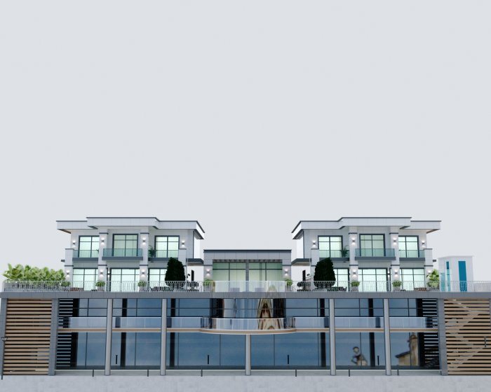
An elevation is the view of the building from outside, without cutting. It shows materials, the position of openings, roof form and levels. Elevations are usually named by orientation or by gridlines, for example the elevation along grids 1–5.
Gridlines, dimension strings and scale
Gridlines are the coordinate system of a drawing. Lines running through the centres of load-bearing walls and columns are numbered in one direction and lettered in the other. The same grids appear on plans, sections and elevations, which lets you link the sheets: what you see as grid B on a section is grid B on the plan too.
Dimensions are usually given in millimetres and shown as strings. The outer strings show openings and wall segments, the middle one the distances between grids, and the outermost the overall size of the building. Internal dimensions are shown separately inside rooms.
The scale is written in the title block in the corner of the sheet, for example 1:100 or 1:50. At 1:100, one centimetre on the sheet equals one metre in reality. Measuring a printed sheet with a ruler is unreliable, because the scale can change when printing. Always rely on the written dimension.
Besides the scale, the title block contains the sheet number, design stage, date and revision notes. Make sure the sheet used on site is the latest revision: a builder working from an old copy can apply a dimension that is read perfectly correctly but has already been superseded. It is therefore useful to move old sheets into a separate folder whenever updated ones arrive.
Level marks and heights
On sections and elevations you will see triangular symbols next to figures such as ±0.000, +3.300 or -1.200. These are levels in metres. Zero is usually taken as the finished floor level of the ground floor, and other heights are measured relative to it.
Remember two distinctions here. Between the finished floor level and the structural level, meaning the top of the concrete slab, there is a difference equal to the floor build-up. Likewise, storey height runs from one floor to the next, while the usable room height runs from floor to ceiling once the slab, suspended ceiling and floor layers are deducted.
Common symbols
A few symbols come up again and again on plans:
- the arc next to a door shows which way it opens and the space it sweeps;
- a window is drawn as thin parallel lines within the wall thickness;
- on stairs, an arrow shows the upward direction, and a broken line marks the part above the cutting plane;
- an outline drawn in dashed lines usually indicates an element overhead, such as a cantilever, a beam or the edge of a suspended ceiling;
- different wall hatching distinguishes materials or load-bearing walls; the explanation is in the legend on the sheet.
What to check as a client
The goal when reading drawings is not to check the structural engineer but to confirm that the house suits your life. A few practical checks:
- Picture the furniture in each room: is there a passage on both sides of the bed, and does a wardrobe door clash with the room door when opened?
- Look at the sill heights: does the window behind the kitchen worktop start above the worktop?
- On the section, is there enough headroom where you pass under the stairs?
- Are air-conditioning units, flues and roof drainage shown on the elevations?
- Do the dimensions of the same window match on the plan, section and elevation?
If you find a symbol you do not understand or an inconsistency, note it with the sheet number and pass it to the designer. A correction at this stage stays on paper; on site it means demolition.
In Zaferoğlu İnşaat's architectural design service, drawings are presented together with sketches and computer models so clients can compare the plan with the three-dimensional form. You are welcome to discuss questions about your project documents with us.
News